Dynamic Perception nanoMoco hardware and software - a first impression
In my last post called "Introduction to time lapse photography" I explained the basics of time lapse photography in combination with a automatically controlled Dynamics Perception dolly. The use of a time lapse slider gives you the possibility to control the motion of your camera in one linear direction. But what about controlling the pan and tilt axis of your camera? Or when you want to rotate your complete subject while you are creating a time lapse sequence? You need to control more motors when you want to create these effects. The soon to be released nanoMoco electronics with it's accompanying software can form a solid basis to create a platform for multi axis motion control.
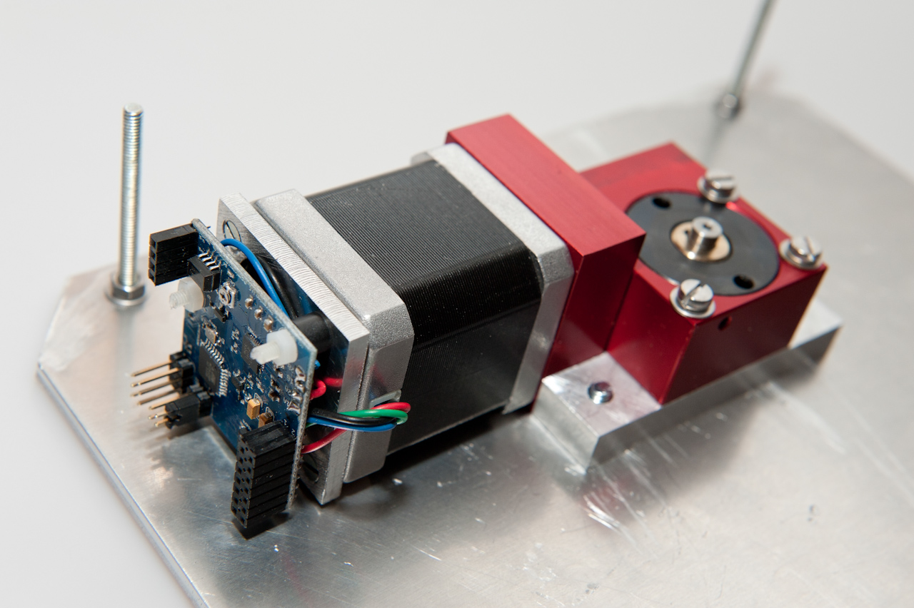
The Dynamic Perception nanoMoco hardware was announced on July 2011 on the OpenMoco forum. This very small 1.5"x1.5" board holds all the electronics to control one stepper motor and one camera. The board is so small that it fits at the back of a Nema17 stepper motor as I mentioned in this forum post. One of the great features of the board is that you can daisy-chain them via the so called MoCoBus protocol. Board are daisy-chained via Cat5 cables. That way you can control an array of motors and camera's from just one central application. You need a connector board that is connected to the nanoMoco board in order to have an easy way of connecting all the cables. In this article I want to show you my connector board for the nanoMoco board. We will see the board in action on my self-made rotary table. Note that this is just the beginning. Dynamic Perception will release these boards soon from now together with new motion control equipment. We will of course offer these boards and the accompanying hardware in our store.
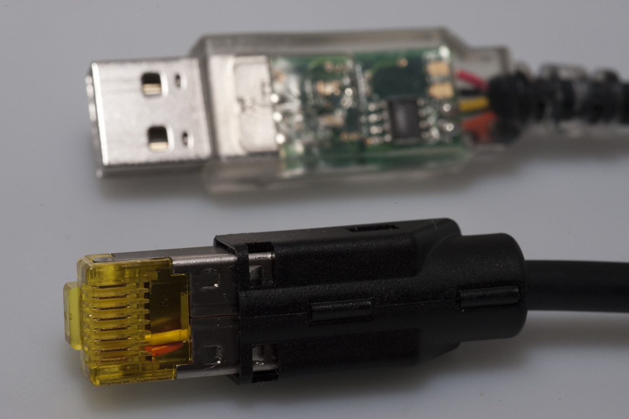
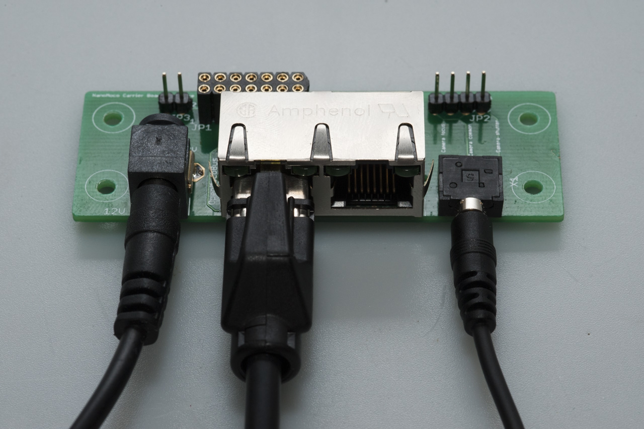
The board is connected to a controller, like a laptop, via a USB->RS485 cable. This cable will convert the USB signal to the RS485 signal that forms the basis for the MoCoBus protocol. The actual connectors of the MoCoBus are based on RJ45, network type, connectors. The first thing was to connect an RJ45 plug to the mentioned USB->RS485 cable. I used a Hirose plug for this since this plug holds a strain relief collar which makes the resulting cable much more durable. The connector board has two RJ45 jacks. The second one can be used to daisy-chain the board to other nanoMoco boards.
 |
 |
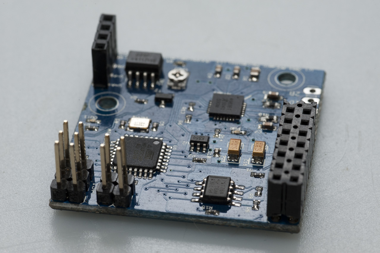
The actual nanoMoco board is small, very small. The following features of the nanoMoco board are taken from the original announcement:
- The controller/driver has an ATmega328p chip and is compatible with the Arduino IDE - you can upload sketches using the TTL serial interface, or burn them directly with an ISP header. However, for long multi-node networks of devices, the board has built in RS-485 using the standard Arduino hardware serial libraries. (Well, you have to control the driver enable line when writing, but a simple wrapper function takes care of this.) A simple jumper will disable the RS-485 network to allow normal use of the TTL serial lines. You can use either type of communication with a computer using one of several inexpensive USB adapter cables.
- Also on board is an A4983 bi-polar chopping stepper driver from Allegro. The CPU has control over the step, dir, each microstep, and enable lines on the driver. In theory, one could go up to 2A/coil but that would be unrealistic with a board this small, unless one had extensive cooling capabilities. Max use would be recommended at 1A/coil. Voltage input range is 8-16V, and an on-board regulator is provided for 5V needed to run the uC.
- With the RS-485 network you can use as few as two wires (A+B) to communicate over several meters. Each node is fail-safe terminated for 16 node network over short runs of cable (a couple of meters), or 8 nodes at longer distances (several meters). The SN75176A buffer is used on each node. Or, some of the GPIO pins have been labeled specifically for interconnects between boards. These are designed to be shared real-time control lines for the devices to trigger actions among themselves during the execution of their programs. RJ-45 cabling will work well in a daisy-chain fashion between the nodes.
- For camera control, there are two opto-isolated outputs.
- There are 5 GPIO pins generally, or 8 if you don't use certain functions of the board, like the opto-isolated outputs or ISP programming. Two of these are connected hardware interrupt lines, and thus can be using for interrupt-driven signaling between nodes, or for encoder input for more accurate stepper control.
- There are also pins marked to monitor the status of the exposure output (one of the isolated outs) and the driver enable line. The exposure watching line is from a transistor-switched control, and therefore can both drive the OK at correct current and a bright LED without damaging the 328's output pin. One input is conveniently placed next to a GND pin to allow for use as an (non-interrupt-driven) input. There are additional 12V and GND pins as well.
The big advantage of the nanoMoco board is that it holds all of this in a very small package. You don't need to use a separate Arduino, stepper controller and electronics to fire your camera. This is all included on the 1.5"x1.5" board. Dynamic Perception has even tweaked the optiboot bootloader that is used by the Arduino Uno. This new version of the optiboot bootloader makes it possible to upload new firmware versions to the nanoMoco board via the USB->RS485 cable. You don't have to do anything special for this in the Arduino IDE, just select Arduino Uno as your target platform.
 |
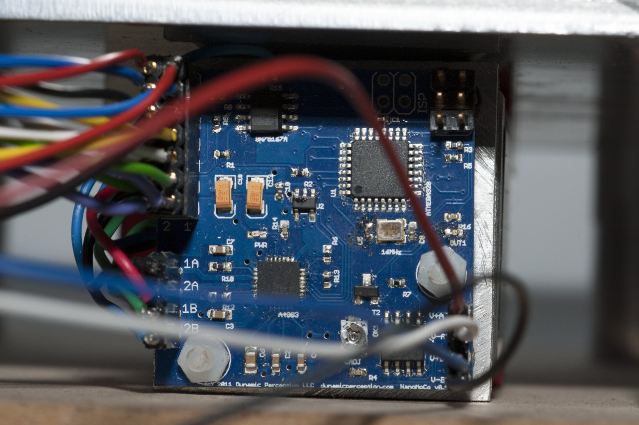 |
| This is the Dynamics Perception nanoMoco board. There are many connections on the board that you can use to connect your camera, the MoCoBus RS485 cable, a stepper motor, status LED's and more. | Here you see the nanoMoco board at the back of a Nema17 stepper motor. All the wires are connected to our nanoMoco connector board. |
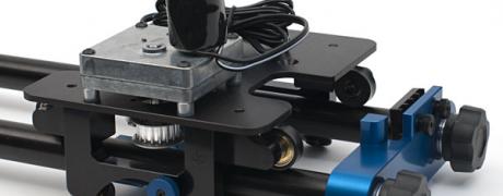
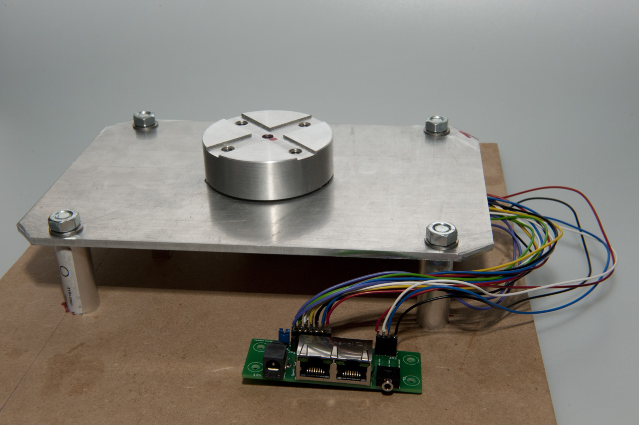
I have used the nanoMoco board on two different DIY projects. The first one is my stepper based time lapse dolly. The second one is my, still to be completed, time lapse rotary table which you can see on the images below. The rotary table consists of many custom parts that I milled myself. The basis is a Nema17 motor that holds the nanoMoco board on its' back. The motor is combined with a 1:120 worm wheel gear box. There are many advantages of using such a gear box. You get a very reliable combination that can do a full 360 degrees rotation of the rotary table in 96.000 steps. Another advantage is that the output shaft has a 90 degrees angle to the motor shaft. This makes the resulting drive train reasonably small.
 |
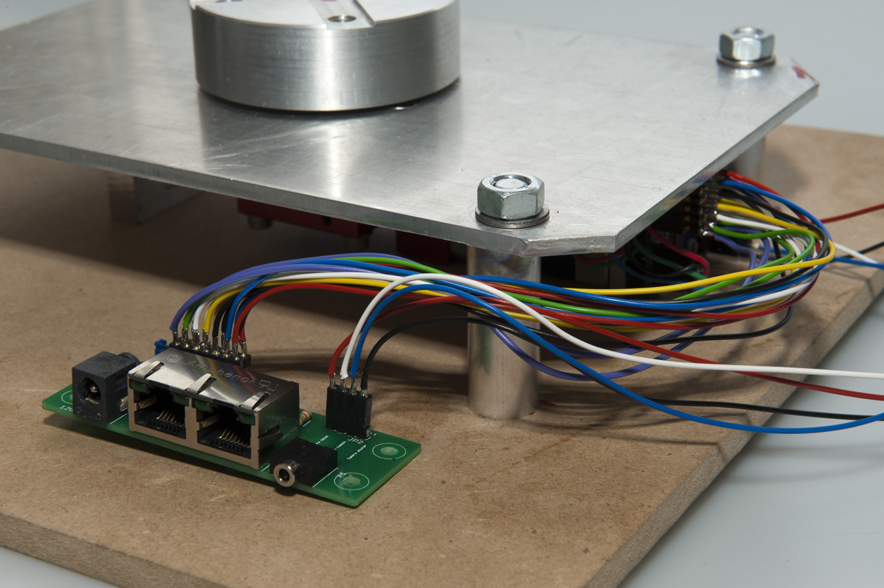 |
| The top plate and the mounting disk of the rotary table with a lot of wires sticking out. | Here you see the nanoMoco board connected to the connector board. The connector board can be mounted in the site plate of the housing. |
I still have to complete the housing, but the top plate and the disk on which you can mount all sorts of equipment, like a camera or a table, is complete. I will post a more detailed blog about the build of this rotary table when I have completed the other parts. We have tested the rotary table during two week long time lapse sequences. The results look very promising since operation is smooth and because of the very high resolution of the rotary table.
 |
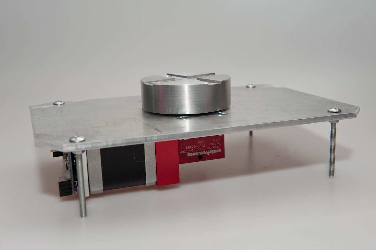 |
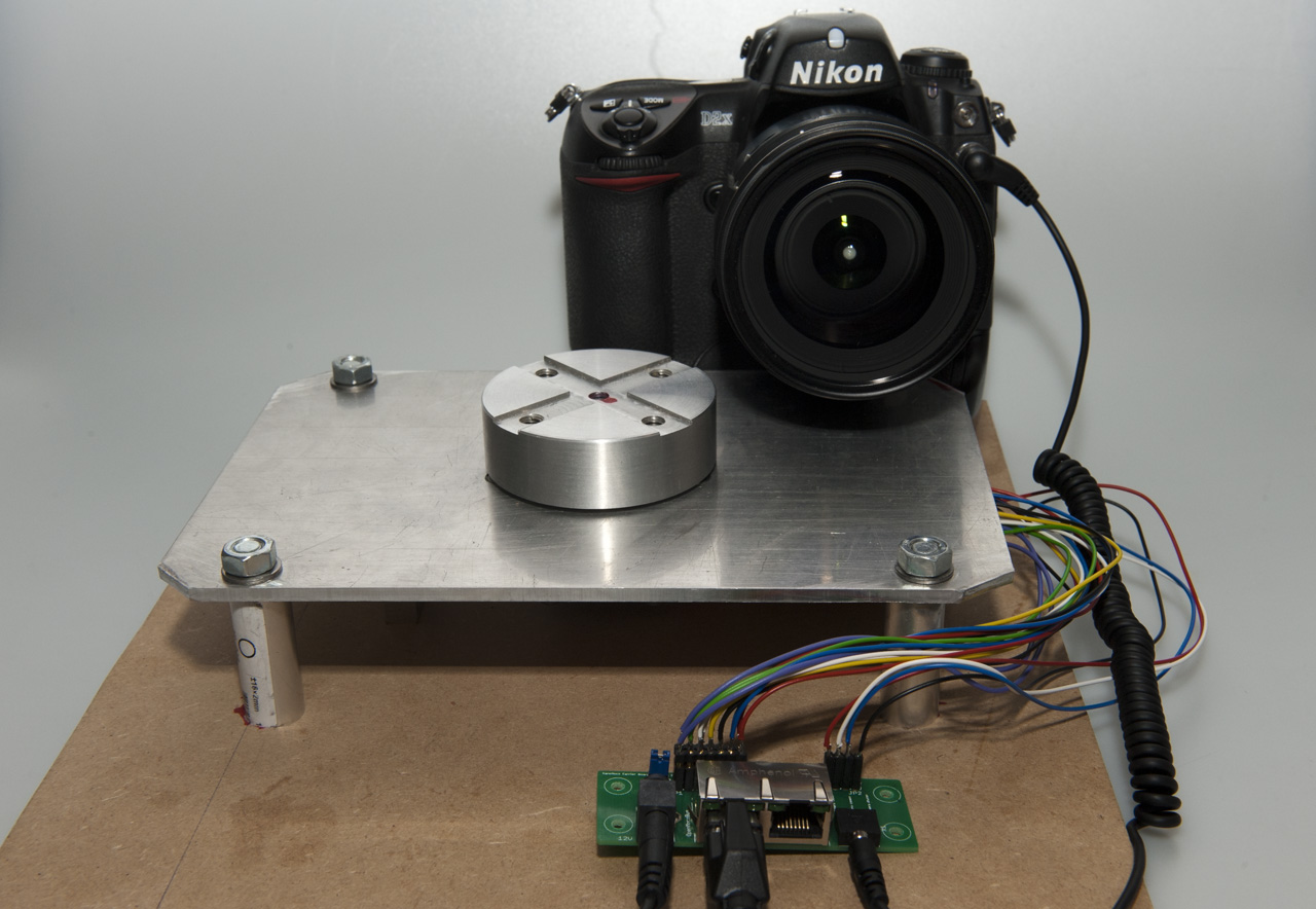
| The nanoMoco based rotary table connected to a laptop, the power supply and a Nikon camera | A clear view of the rotary table build. The top plate acts like a chassis that holds all the major parts. |
Using nanoMoco based time lapse equipment
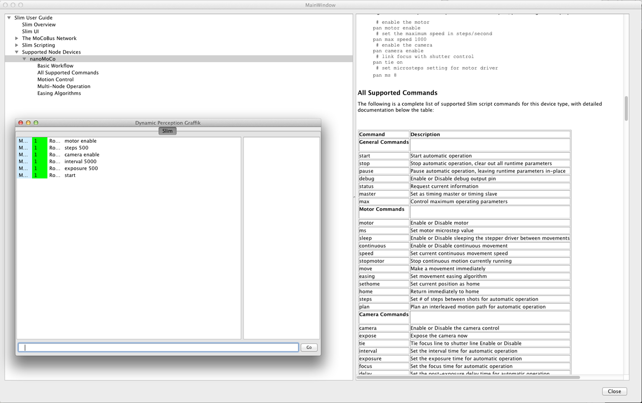
Previous version of the OpenMoco based time lapse engines used Slim to control the motors. Slim is a Perl based command line driven application. Using it is not too hard but it can still be daunting for a lot of users. There will be a fully graphical controller application in the future, but that is still under development. In the mean time we can use the new application called Graffik. Graffik is an open source controller application that is written especially for the nanoMoco hardware. A big advantage of the software is that it runs on all majors platforms like Windows, Linux and OSX. With Graffik you can control as many MoCoBus busses as you can. This is only limited by the number of USB ports on your computer. Each bus can hold up to 253 MoCoBus compatible devices. You first have to define at least one bus and one device before Graffik can control your device.
 |
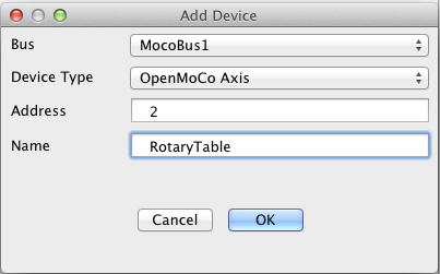 |
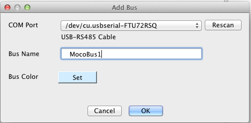
| Here an MoCoBus with the name MocoBus1 is defined. This bus is connected to an USB-RS485 cable as you can see. | A device with the name RotaryTable is defined for MocoBus. The address of the device on the bus is 2. |
The rotary table is now ready for action. You can enter commands to do so. These commands are slightly different from the original Slim commands. That is a good thing since the commands are now much more logical and consistent. Graffik has a very extensive help function. I find it helpfull to have the help on the background. That way you can quickly learn how to use it all. The following shows a few commands that are needed to use the rotary table with a 5 seconds camera interval.
Conclusion
I have used the nanoMoco boards for months now and I can only say that these boards are very impressive. The board really holds all the electronics that you need for the creation of a complete motion control setup. The current firmware version is very stable and has given me no issues. I cannot wait until Dynamic Perception will release motion control products based on the nanoMoco and MoCoBus technology. The openness of the software and especially the MoCoBus protocol clearly gives this system an advantage over proprietary solutions. It is very feasible to create your own MoCoBus compatible solution. There is a DMX lighting solution under development that will be MoCoBus compatible. We as ElysiaVisuals are working on an MoCoBus USB camera controller with very exiting features like high shutter speed ramping with shifting ISO or shifting aperture values.
related products - Related Products
- Log in to post comments