Nikon D700 high speed exposure ramping with ISO shifting - Maasboulevard Rotterdam

I have mentioned the technical aspects of exposure ramping with a Nikon camera before on my blog. The has resulted in a lot of work for me the last month. The result is a ramping solution that works on both Nikon and other brands like Canon. The video that you see on this article is the first real outdoor test of my ramping solution. You are seeing the Maasboulevard, one of the main roads that bring you into the center of Rotterdam. This sunset video is made my continuously ramping the shutter speed of my Nikon D700 from 1/100 of a second until 2.5 seconds. The ISO is also ramped from 100 ISO until 1600 ISO at the end. This results in a total exposure ramping of 12 Stops between the first and the last image of the sequence!
The camera is controlled completely automatically by my solution. You just enter the parameters that you want for the run and that's it; just wait an hour. The camera is set into manual by the controller and the start ISO is set too. Then the shutter speed is set on the camera that is closest to the desired, or calculated, shutter speed. This will result in differences between the actual, discrete, shutter speed on the camera and the shutter speed that you really want. This is compensated by generating XML files that correct each image automatically in Adobe Lightroom as soon as you export the image for further processing in Adobe After Affects of something similar. The camera is automatically set into bulb when the shutter speed gets longer. Nikon camera's are way off in their bulb mode like I explained before. I therefore measure the actual shutter speed via the PC socket after which I can also create XMP correction files. The ISO is shifted also, in this example when the shutter speed is higher than 2 seconds. Then the ISO is doubled and the shutter speed is cut in half. Again, this is all controlled automatically by my ramping solution.
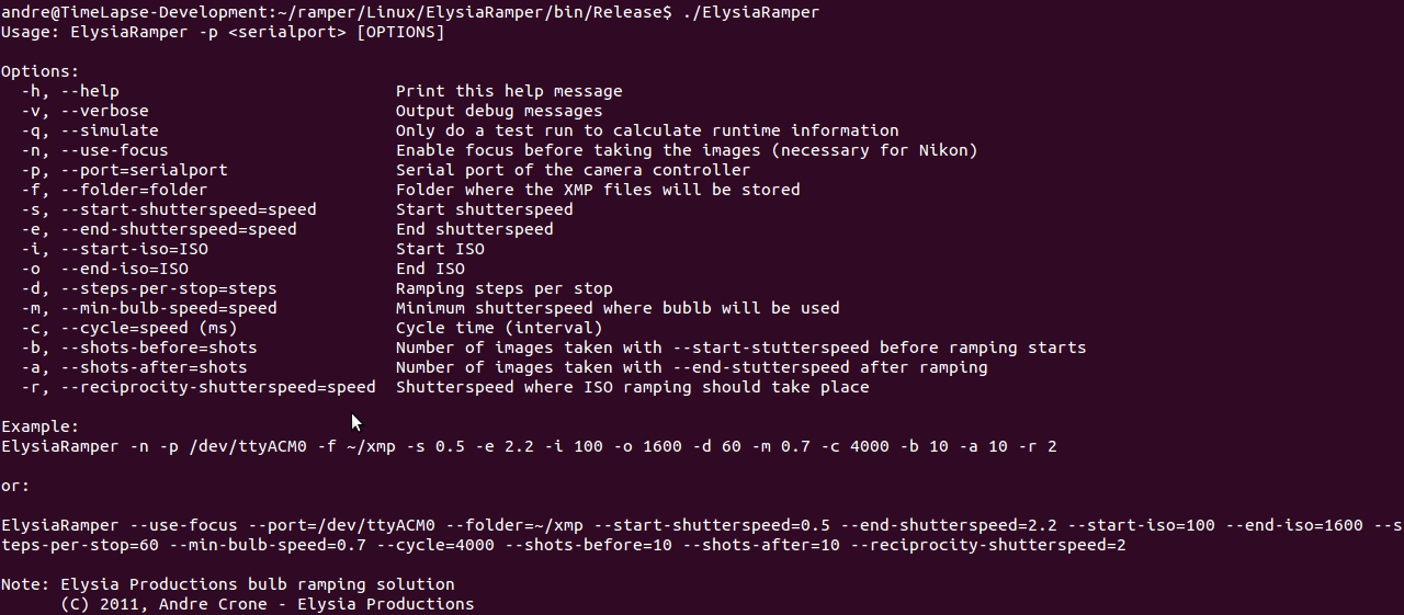
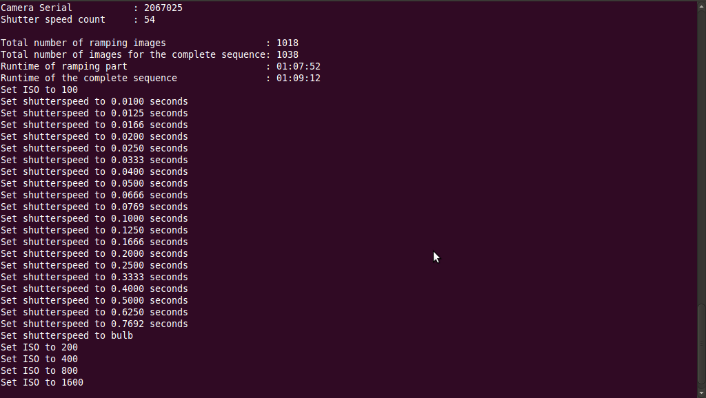
The solution consists of an Arduino based controller that is connected to a Linux based Netbook computer. The Arduino controller fires the camera and measures the actual shutter speeds. A "server" application on the laptop communicates with the Arduino controller. This laptop application controls the exposure mode, shutter speed, bulb mode and ISO of the camera. The Linux application now acts as a front-end. You just enter the desired parameters on the command line and it will all start running. The controller first detects which image number the camera will use next, so that the XMP files have the correct names as well. The camera brand and model are already automatically detected by my application. I will use that information later to implement camera specifics. My current version only works on a D700, but it is very easy to extend this to other models or brands. Below is a screen shot of the command line application that I used to create this video:
Planning your shot and entering the correct values was not easy. You enter start and end values for exposure and ISO. You also have to enter the number of steps that you want to ramp per stop. That all results in your time lapse sequence. At first it was a bit hard to predict how long you run will take and how may images your camera will shoot. I therefore introduced the --simulate parameter. That will only simulate your run and a small report about the number of images and the total runtime of your sequence is printed as you can see below:
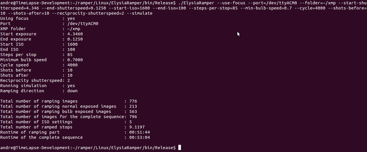
The following screen shots shows the output of the actual run that I had when this video is created. You see that half of the shoot is made by using the normal shutter speeds and half by using bulb mode:
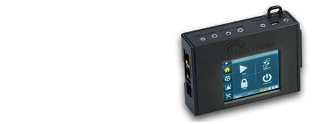
So, what's next? I think there is room for an even better quality of the video. It looks like there are (very minor) flickers at the beginning of the sequence. It will take some hard core programming, but I can iron them out I think. I also want to ditch the laptop. The end result will be an OpenMoco compatible controller that is hand held. This will involve a lot of electronics since I have to include a small embedded Linux board as well. I can then combine this controller together with my NanoMoco based dolly. All these components can communicate with each other via an RS-485 based MocoBus. There is still a lot work to do! But I have my ramping solution that I can use in the meantime.
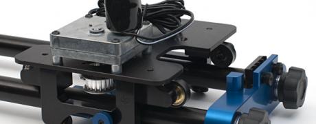
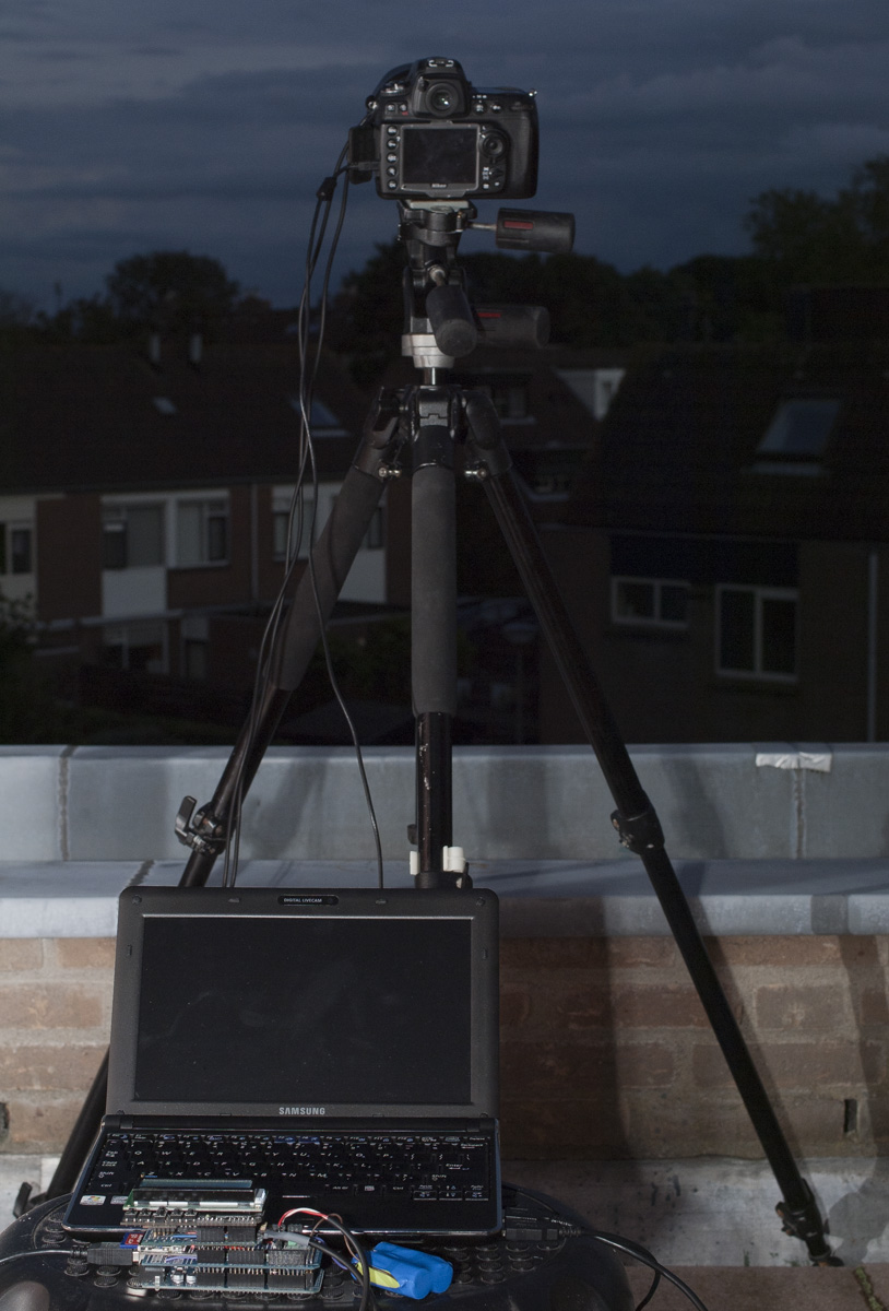
Let me end with an image of the curent setup. The be shocked by the complexity. This all started out as a proof of concept. I guess whe passed that phase. It is time to move on to a more streamlined version.
- Log in to post comments