MicroEngine for studio time lapse photography
Ok, I promised some hardware projects that I would publish on my blog. This is certainly photography related, but a bit technical for most of you I guess. The first piece of hardware is my studio time lapse photography engine. More projects will follow, but not all of them will be open source, open hardware like the MicroEngine. The software that I have written for the device is open source under the GPL license.
What is the MicroEngine
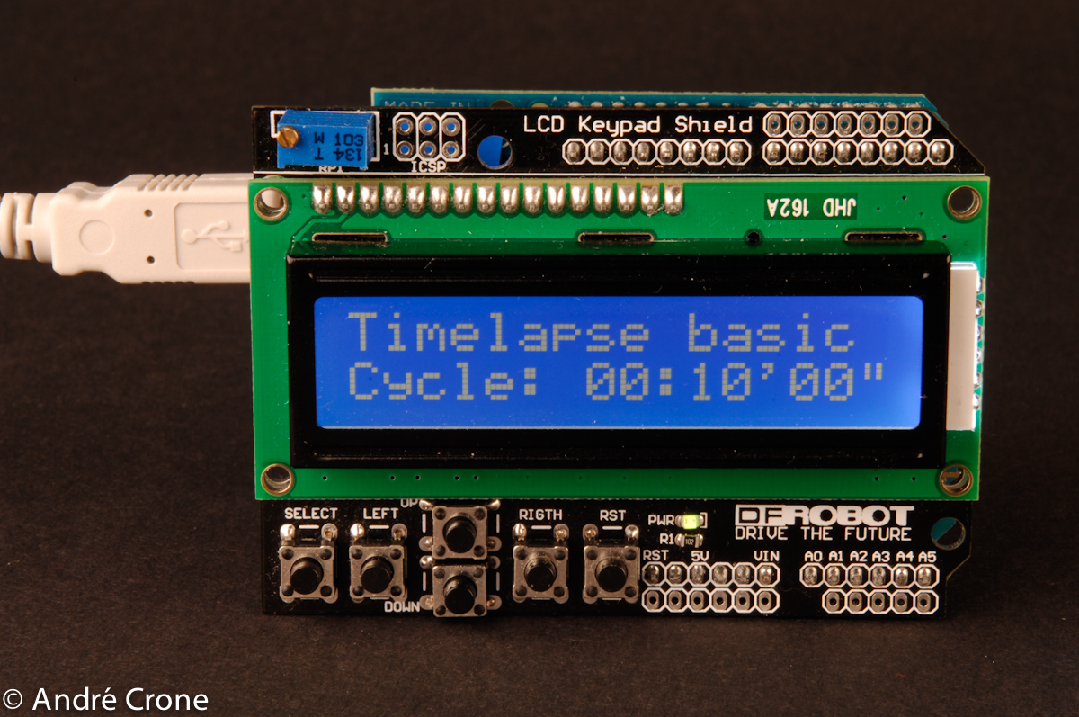
The MicroEngine is a small light weight time lapse engine based on an Arduino and the DFRobot LCD Keypad Shield. The project was started in order to learn more about programming Arduino's. The aim was to have a small device that can be used to create time lapse sequences in a studio. The more advanced digital cameras have time lapse functionality built in. Although I must admit that my D2X and D700 are hard to configure when I want to take a time lapse studio. You are much better of with an external trigger that is easier to use. Studio time lapse sequences need more functionality than standard trigger offer. The most important features of the MicroEngine are:
- Basic time lapse function with a delay between 1 second and 24 hours.
- Advanced time lapse function. This function can trigger relays before the actual image is shot. I use it to power off plant growth lights and to power on studio strobes. That way every image is taken under the same conditions. These on/off functions can function within certain time frames of the day.
- Built-in real time clock (RTC)
- Studio setup mode where all relays are powered on.
- Camera remote control. A bulb shutter speed of 24 hours can be set.
- Lightning based camera trigger (under development).
- Laser trigger that can be used for high speed photography (under development).
- Support for Nikon focus tab.
- Configuration is stored in the EEPROM of the device.
- Can be operated by using the 5 buttons on the LCD shield
How to build it
The device is built around the following three parts:
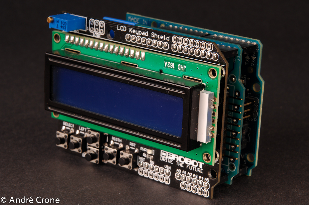
- An Arduino Duemilanove or Arduino UNO.
- DFRobot LCD Keypad Shield. I might create a future version based on an I2C LCD display and separate keypad.
- Home built Arduino camera shield.
The camera shield is used to connect the camera to the Arduino. The current version is based on an Arduino proto shield. The schematics are based on the OpenMoco schematics. The basics for that can be found on http://www.openmoco.org
The software can be downloaded from Sourceforge. Note that the current trunk version is old (at the moment that I am writing this blog). It is much better to use the DEV version. I am only checking in DEV versions that have been tested and that are working. A new TRUNK will be created very soon from now; I only have to tweak some of the real time clock functionality. You are free to contribute and clean up the code is you like.
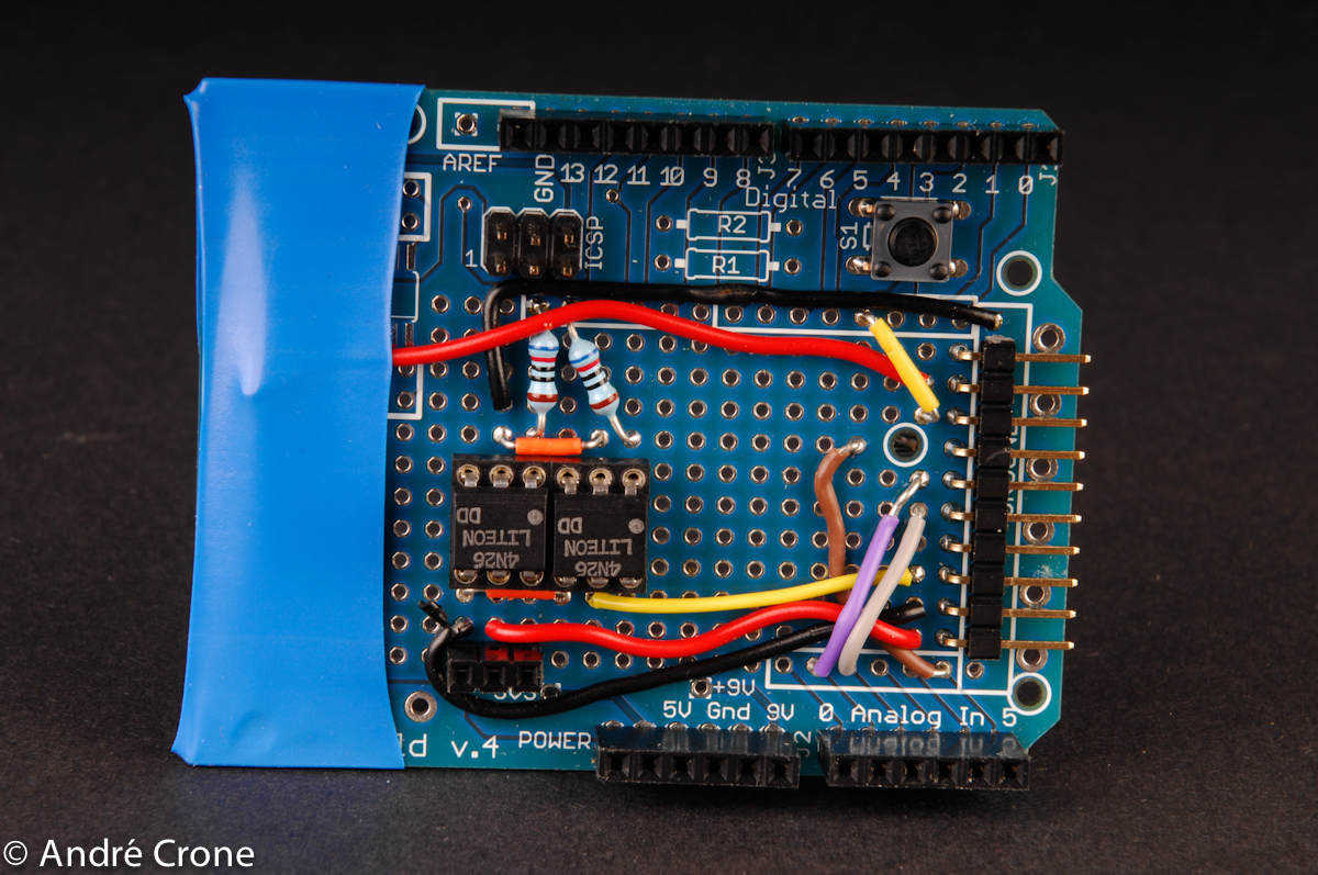
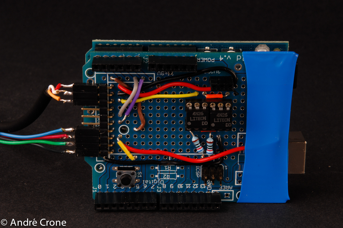
The following image shows the camera shield. Note that you need female headers with long pins so that the shield fits the underlying Arduino. Note that this is a slightly old version of the shield. It is fully based on the schematics that are published on the OpenMoco.org site. You can find the Arduino pins that I am using in the source code of the MicroEngine Arduino Sketch. My current version also holds an I2C Real Time Clock based on a DS1307. I am using a breakout board from Sparkfun for this. The RTC is connected to analog pin 4 & 5 (default Arduino I2C pins). I am not using any pull-up resistors. The built-in Arduino pull-ups are giving me a stable readout of the RTC.

- MicroEngine camera shield
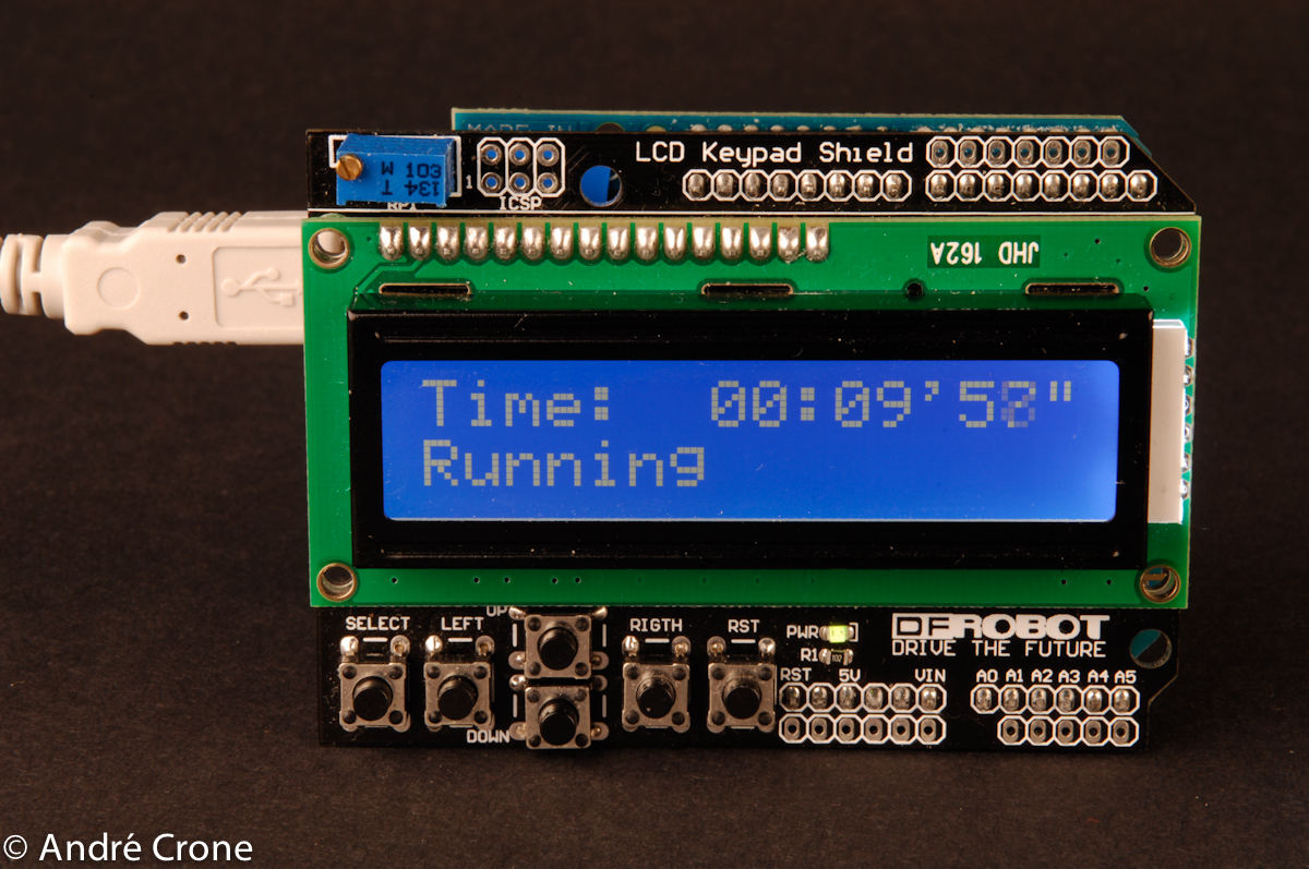
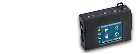
This image shows the device when it is used during a time lapse sequence. You can also see the counter that is running backwards so that you can see when the next image is shot.

- MicroEngine during a sequence
Using the MicroEngine in a studio
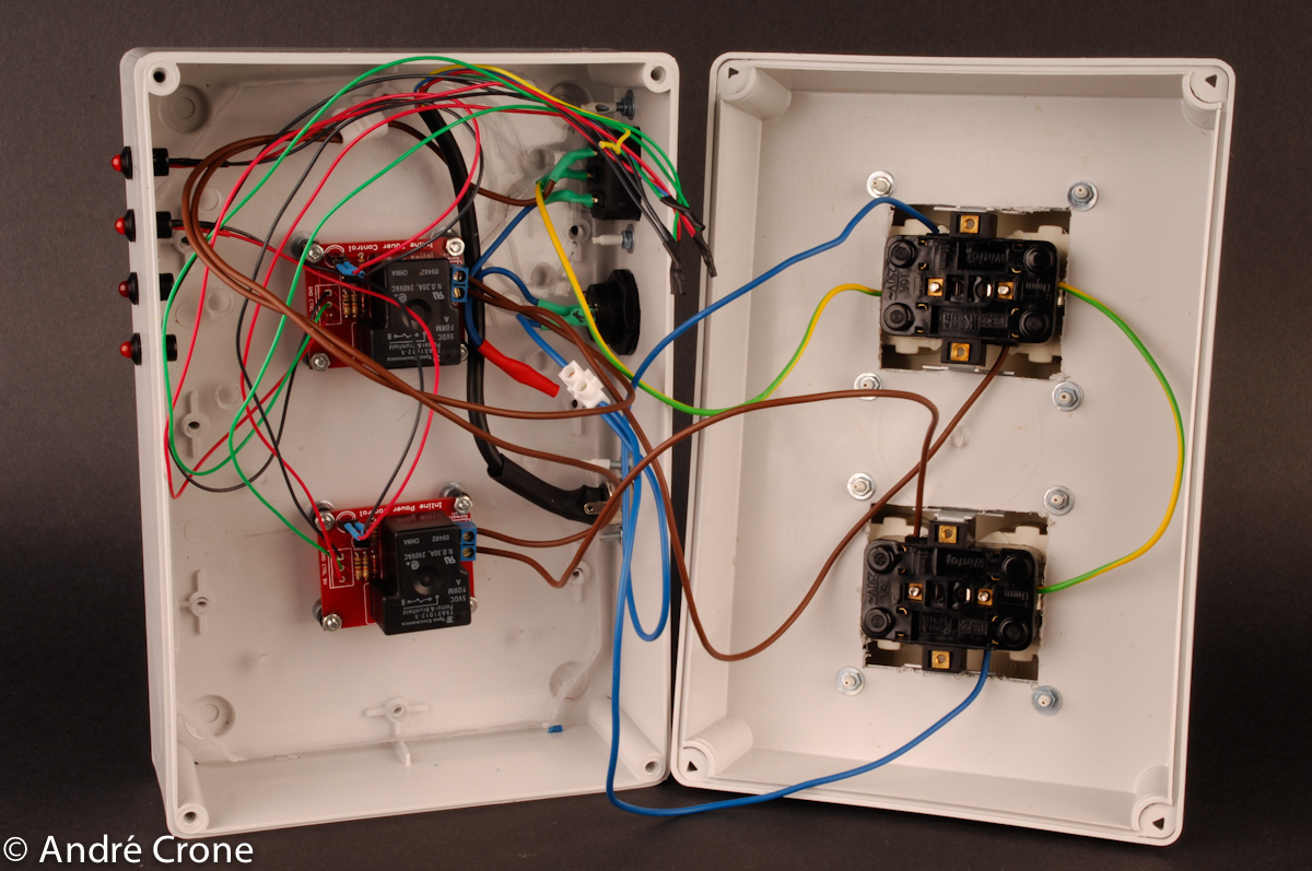
The device can be used to power on/off 220Volt devices with the use of relays. One relay can be set to power off before the shot, one relay can be set to power on before the shot. The time before the actual shot that the relays are put on/off can be set in the settings menu of the device. The following images show the box that I am currently using for this. The relay board can be found on here: http://www.sparkfun.com/commerce/product_info.php?products_id=9096.
The camera shield with a camera and the relays connected:

- Camera shield with connect camera and relays
The inside of my 220V power block:

- Inside the 220V power block
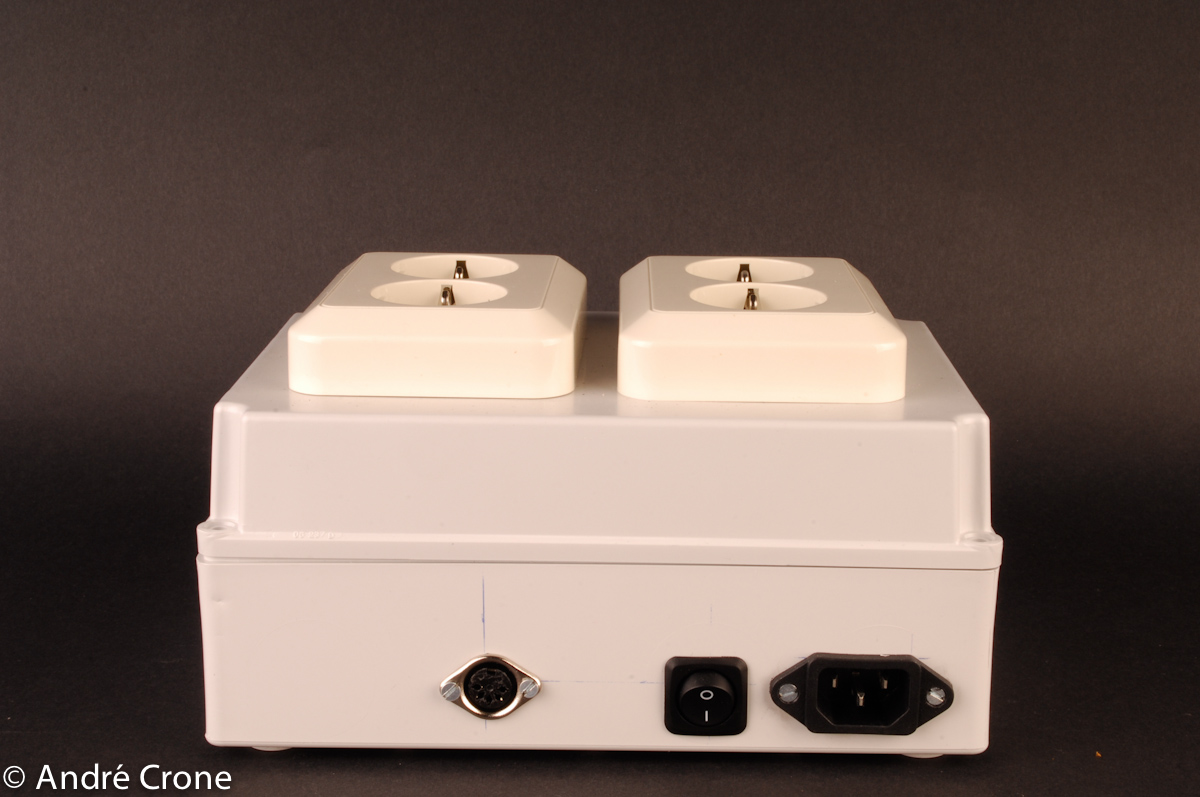
The assembled 220V power block:

- Assembled 220V power block
What is next?
The current DEV release on sourceforge is fully functional. I am only working on the last bits around the RTC. I will have a new V1.2 version at the end of March. That version will hold all the functionality that I had in mind when I started this project.
- Log in to post comments

Comments
users manual Microengine