Interfacing with Motion Control Hardware
 The RamperPro can interface with all current motion control hardware like the Dynamic Perception MX2 and MX3 motion controllers or the eMotimo TB3. You can also use external intervalometer to trigger the RamperPro. That way you can use the DitoGear controllers with the RamperPro for example.
The two ext ports (ext1 and ext2) at the back of the RamperPro can be used to integrate the RamperPro with motion control hardware. There are also two MoCoBus connectors available. These are the double RJ45, network connectors next to the light sensor connector. The MoCoBus connectors are for future use when more MoCoBus motion control hardware becomes available (from for example DynamicPerception).
The first I/O port is tied to camera one, the second one to camera two. You might need special adapters to connect external hardware like our I/O isolator or the ElysiaVisuals DragonFrame adapter.
Its probably best if the RamperPro triggers the motion control hardware to move to the next position. That way you are sure that the exposure is finished and that it is safe to move your camera. This needs to be supported by your hardware. Some hardware like DitoGear hardware doesn't have this possibility. You can then configure the RamperPro to be triggered by an external signal. The motion control hardware can then signal the RamperPro to take a picture. A drawback of this mode is that you cannot use interval fairing because the RamperPro is not dictating the interval.
There are currently three different types of integration possible:
- The RamperPro as the master device. In this setup the the RamperPro determines the timings and it controls the camera. Motion control hardware can be triggered by the RamperPro to move all axis to the next position. This is especially working good in a shoot-move-shoot configuration. A big advantage is that the interval fairing capability of the RamperPro can be used because the RamperPro sets the changing interval. You would need to use the I/O isolator when you use this mode. This isolator acts like a switch that can trigger motion control hardware like the MX2, MX3 and TB3.
- Use an external intervalometer. Some motion control hardware like the DitoGear solutions cannot handle an external intervalometer. In that case you set the external hardware to be the external timer. The RamperPro will then be triggered by that timer.
- DragonFrame integration. The RamperPro features an experimental DragonFrame integration mode. Here the RamperPro acts like a DragonFrame remote controller. It will trigger DragonFrame to move all axis to the next position when a shot is taken by the RamperPro.
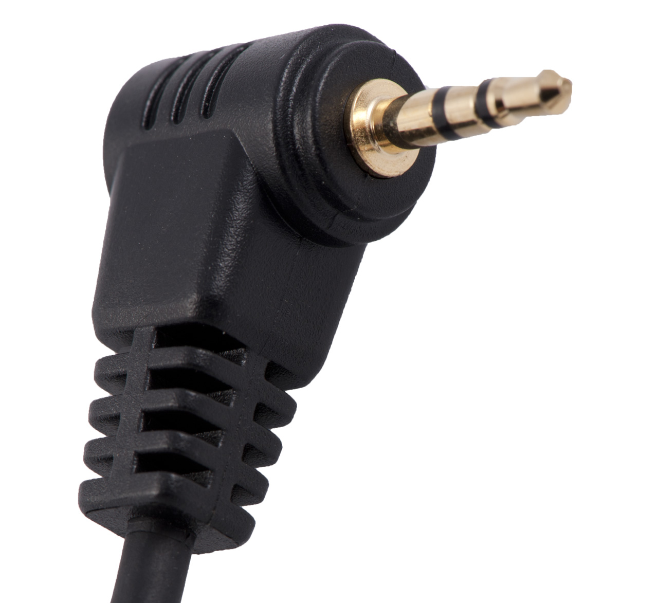
The 2.5mm Tip Ring Sleeve (TRS) plug
You connect motion control hardware to the I/O functionality of the RamperPro with a so called 2.5mm Tip Ring Sleeve (TRS) plug. The tip and ring of the plugs are connected to the RamperPro hardware. You can define the behavior or both this ring and tip in the I/O settings menu in the system menu. There is can either define if the ring or tip acts as an output, needed to trigger an extern system or as an input, so that the RamperPro can receive triggers from external systems.
How to delay the motion control hardware after a shot is taken
You might want to have a (short) delay after a shot is taken by the RamperPro and the moment that the motion hardware is triggered. That way you are absolutely sure that the shutter is closed before the camera is moved. You do this by setting the "Post delay time" on the Camera 1 and Camera 2 system settings in the system settings menu.
Using multiple motion control rigs at the same time
The RamperPro can control two cameras and interface with two motion control rigs at the same time. These cameras can run different ramping profiles and each camera can be put on their own motion control device. You can for example setup a Nikon D800 as camera one on a Stage One slider and you can put a Canon 5Dmkiii as camera two on a TB3 pan and tilt head. The RamperPro can then control both cameras and both the Stage One and TB3. Ext1 is linked to the first camera and ext2 is linked to the second camera. So in this example you would wire the Stage One to ext1 and the TB3 to ext2; use an I/O isolator in both cases.
Integrating with motion control hardware while in 3D/Stereo mode
In 3D or Stereo mode the RamperPro will accurately synchronize two camera’s to virtually act like one camera. This means that you can only receive one external trigger if you are interfacing with an external intervalometer. This trigger will then trigger both cameras at exactly the same time. You might want to connect an external intervalometer to ext1 when you are in 3D mode when you are using an external intervalometer like a DitoGear multi-axis Evolution setup. It is theoretically possible to trigger two motion control rigs in 3D mode when the RamperPro is the timing master. But we doubt if somebody will ever use that possibility. This means that you will most probably always will be using ext1 when you are using the 3D capabilities of the RamperPro.
The following paragraphs explain for each mode how to connect the RamperPro to your motion control device(s) and how to setup the required parameters to make it all happen.
How to use the RamperPro with a Dynamic Perception NMx
How to connect the ElysiaVisuals RamperPro controller to the NMx motion controller from Dynamic Perception from ElysiaVisuals on Vimeo.
How to use the RamperPro with a Kessler Second Shooter controller
Using Ramper Pro with Second Shooter from Kessler Crane on Vimeo.
Connect the RamperPro to motion control hardware
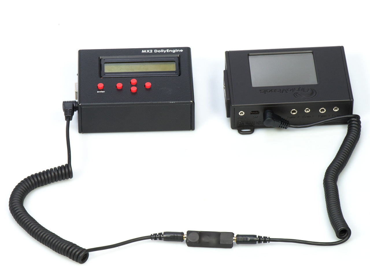
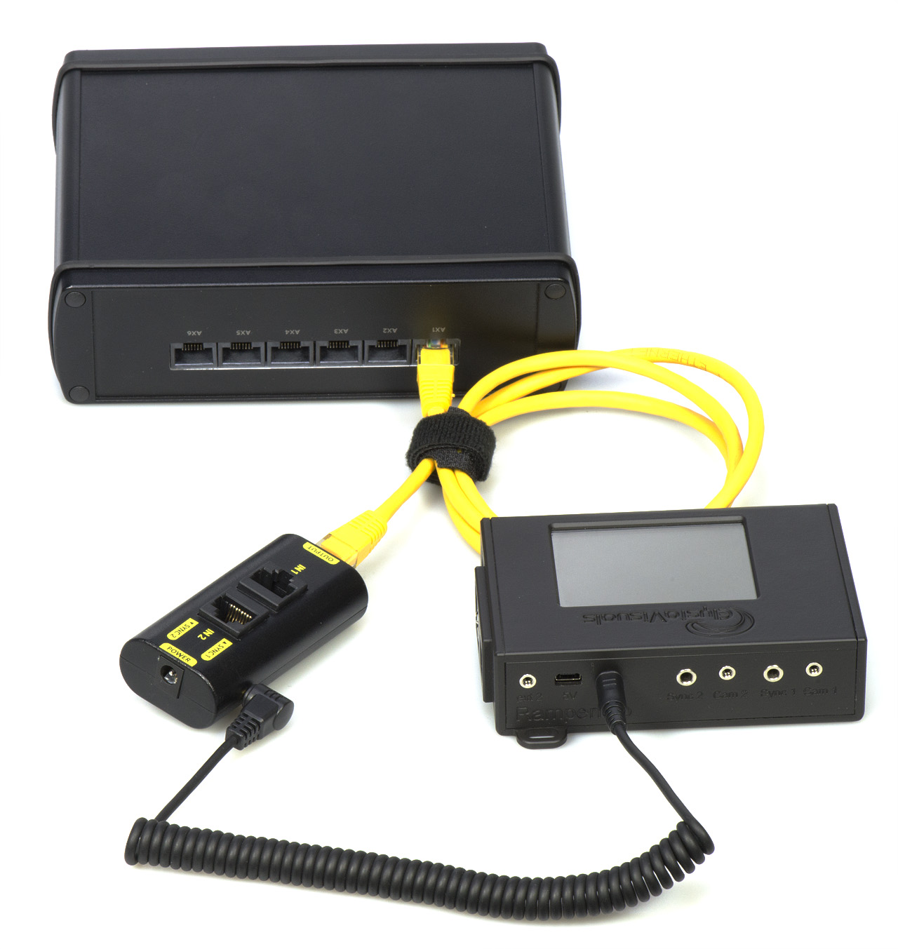
Most motion controllers expect some sort of external switch when they integrate with the outside world. The RamperPro can provide this external switch with the help of the ElysiaVisuals I/O Isolator. This is a tiny solution that you connect connect between the RamperPro and controllers like the Dynamic Perception MX2, MX3 or the eMotimo TB3. Please take the following steps when you are using this kind of interfacing:
- Connect one cable to the desired ext (1 or 2) port of the RamperPro. Ext1 is linked to camera 1 and Ext2 is liked to camera 2.
- Connect the other end of this cable to the input side of the I/O isolator. That is the side that has no indicator.
- Connect a second cable to the output side of the I/O isolator. That is the side that has the O of output visible on the connector.
- Connect the other end of this cable to the I/O port of your motion control device.
You now to to configure both the RamperPro and the motion control device in order to get the integration to work. Use the lowest possible interval on the TB3; this will indicate "External" on the display. Refer to the manual of the Dynamic Perception MX2 or MX3 about how to configure these motion controller to receive external triggers (either via the ring or tip of the cable).
The TB3 will be triggered by the tip of the TRS plug. This means that you need to configure the tip of the TRS plug in the I/O settings menu. Set the value to enabled=yes, input=no, DragonFrame=no and a trigger time of 50ms. The MX2 or MX3 can "listen" to both the ring or tip.
The I/O settings can be found in the system menu of the RamperPro (icon with the two tools on it). Then press the arrow down in the button bar until you find the icon called I/O. That will bring you to the I/O settings. There are 4 different pins (two per camera). You can reach these by pressing the up or down buttons on the I/O setup screen.
 |
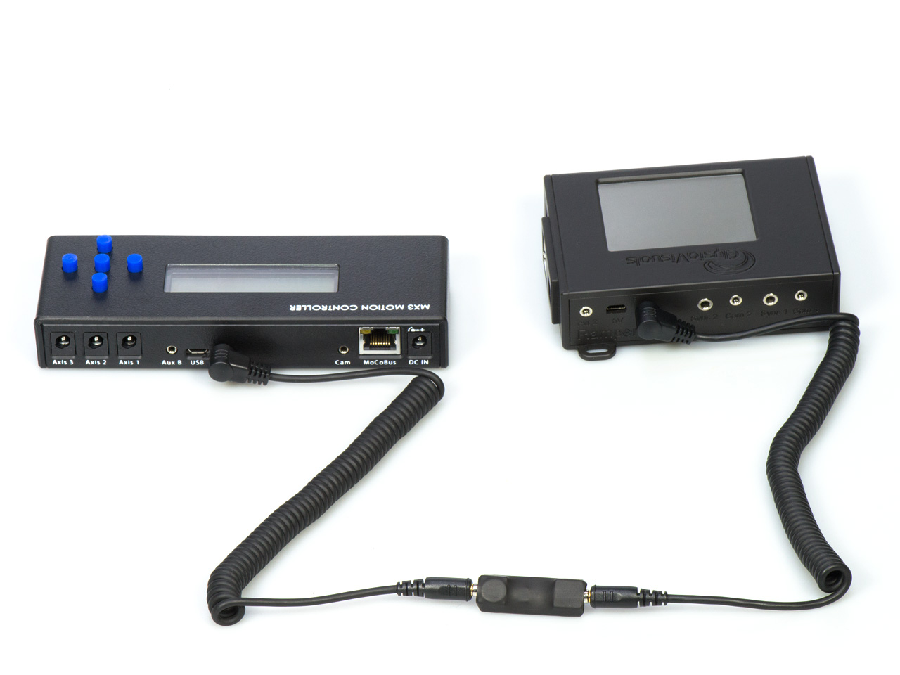 |
| The RamperPro connected to the MX2 motion controller. Please note the direction of the O on the I/O isolator. |
The MX3 can also be connected to the RamperPro. This gives you a three axis motion control solution. Please note the direction of the O on the isolator. |
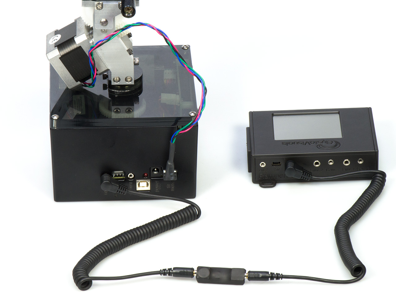 |
| The I/O isolator can also be used to interface the TB3. This way you get a three axis stepper motor solution. The RamperPro will trigger the TB3. This way the axis can move to the next position when the RamperPro has fired the camera. |
How to use the RamperPro stepper driver
How to setup and use the RamperPro stepper motor driver from ElysiaVisuals on Vimeo.
Using external intervalometers
External intervalometers can be used to trigger the RamperPro to take a picture. This is only valid in exposure ramping mode since it makes no sense to have an external trigger when you are running the RamperPro is basic mode. Please take the following steps when you are using this kind of interfacing:
- Connect a 2.5mm double TRS cable to the output port of your external intervalometer. That is the port that you normally use to trigger your camera.
- Connect the other side of this cable to the desired ext port of the RamperPro (as described above).
You now need to set the appropriate settings on the RamperPro so that it will listen to the external trigger. You do this by configuring the tip of the connected Ext1 or Ext2 cable. The trigger is received by the tip of the cable. This means that you need to configure the appropriate tip I/O settings to: enabled=yes, input=yes.
 |
| You don't need the I/O isolator when you connect an external intervalometer. Here you see that the camera port of a DitoGear controller can be plugged directly into the RamperPro Ext ports. |
Interfacing with DragonFrame
The RamperPro can act as a remote control for the fantastic DragonFrame stop motion software. In this setup you can use DragonFrame to control you stepper motor based motion control rig. This has many advantages but the most important one is that you can create highly advanced multi axis moves based on key frames with DragonFrame. DragonFrame runs on both Windows and OSX computers and it communicates to the outside word like the RamperPro via the USB port. You cannot connect the USB port of the RamperPro to the USB port of a normal computer. That is why we have developed the RamperPro DragonFrame adapter. This is a small adapter that you can use to connect the RamperPro to a computer that runs DragonFrame.
Note: The DragonFrame adapter uses both the tip and rind of the Ext connector since the interface can both send data to DragonFrame, but it can also receive data from DragonFrame. That is why you will see "DragonFrame is enabled of the previous pin" when you try to set the settings of a tip when the corresponding ring of the plug is configured to be a DragonFrame connection. Set the ring of the I/O port to enabled=yes, input=no and DragonFrame=yes when you want to configure the RamperPro to be connected to DragonFrame.
This is how you connect the RamperPro to a computer that runs DragonFrame:
- Connect a cable to the desired ext port of the RamperPro.
- Connect the other side of this cable to the RamperPro DragonFrame adapter.
- Connect a mini USB cable to the other side of the RamperPro DragonFrame adapter.
- Connect the other side of the USB cable to the computer that runs DragonFrame.
You now need to configure the RamperPro so that it will trigger DragonFrame whenever an image is taken. That way DragonFrame can move all connected axis to their next position. You also need to setup DragonFrame in such a way that it will listen to a USB port for external commands to get this working.
The MoCoBus and NMx
The open source motion control bus (MoCoBus) is an exciting development that will make it possible to daisy chain various motion control devices. The DynamicPerception nanoMoCo enabled stepper motors are an example of this. You can daisy chain up to 16 of these stepper motors and you can control them via one single RJ45 cable. There will be more devices that support the MoCoBus protocol (like easier to use motor) in the near future. The double MoCoBus connectors at the side of the RamperPro are for future use. Support to control nanoMoCo and derived stepper motors will be added to the RamperPro firmware in the future. That will make the RamperPro a highly advanced motion controller that both controls your motors and your camera!